
Prototype
This is a set of pictures with explanations to show how the first test version was put together to be a voltage and current monitor.
Software to implement these ideas can be viewed on github here.


The ESP01 connector doesn't lend itself to using the standard matrix board layouts and so an adapter was made specifically for this.
After this I found a source of cheap matrix board which could accommodate the 4x2 header required for the ESP01 so these adapters weren't necessary.


Pictures showing putting the components onto a small piece of matrix board to test the layout. The picture on the right shows how the pins are positioned with respect to the traces.


The size of the board is set by my self-imposed case limit, not any other so could be adapted to a large board and case. In the pictures, the power is supplied via a dual terminal block but in future version sis via a 5.5mm power plug.
The picture also shows the socket adapter for the ESP01 and the buck convertor power supply in place.
The dual pin header shown is to disconnect the power to the module to be used, originally meant for testing different modules but in this case the module was soldered in place so wasn't useful.

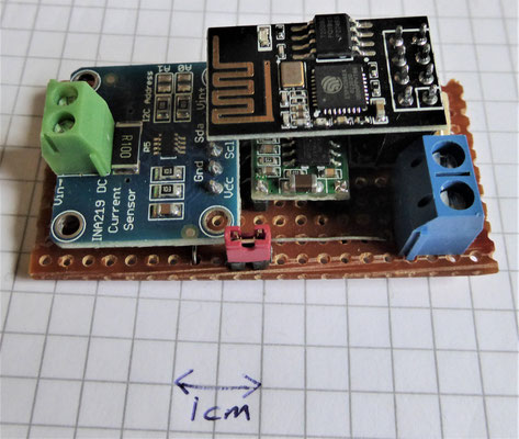

The initial module used for testing was an INA219, but a mistake in soldering the terminal block on the same opposite side as the connection pins meant that couldn't be fitted via plug inside the case. Future implementations use a miniature barrel connector so that the terminal block doesn't need fitting and connections are easier.
The pictures then show the completed module with ESP01 assembled.


These final pictures show the module inside its case. This is very much a testbed implementation and will be used for trying other things out.