
Wall Display

I bought a cheap pocket watch meter from eBay thinking that it would make an interesting novelty item. It turned out that the meter I'd bought wasn't suitable, but by then I'd committed myself to producing something which would hang on a wall and be a talking point.
For Sofware and any additional information see github
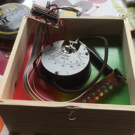
The centre of the display is an analogue ammeter which is energised by a charged capacitor which discharges through the meter animating the pointer needle in doing so.
An LED display mirrors the movement of the pointer providing an eye catching display.
The whole is controlled by an Atmel 328 microprocessor, directly developed on an Arduino Uno, which measures the current light levels in the room, and randomly triggers the display, all powered by three AA batteries.
Supplies:
Arduino Uno with Atmel 328 processor...see rest of text
Selection of LEDs, Red, Green and yellow with one White
7 x 330R resistors
1 x LDR
1 x 220uF capacitor
1 x 220R resistor
2 x 10k resistors
1 x rectifier diode
A suitably old ammeter, typically 100uA full scale


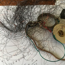

The pictures tell a short story, the original meter was designed for use on valve radios and required over 100mA and just couldn't be run by an Arduino. These are early display layout ideas. In the end I took the meter apart with the intention of replacing the mechanism, not very successful.
Eventually I picked up an old voltmeter with a 100uA mechanism, perfect.


The original build used an Arduino to connect the bits in what is a fairly simple system. Six digital pins drive the coloured LED's via 330R resistors.
One digital pin is used to energise the LDR voltage divider, the voltage being measured on one of the ADC pins and used to estimate the current light level and the time of day.
One digital pin is used to charge the capacitor via a diode and 220R resistor.
The meter is connected across the capacitor via a 10k resistor. This value may need to be changed depending upon the full scale measurement on the ammeter used.
I also wired in a reset button, to be mounted on the side of the display case.
Lastly, a further connection is made from the anode of one of the LED's to provide a voltage reference to check the battery voltage level. This circuit has never been very successful and I'll change it to a simple voltage divider the next time the batteries run flat and the display is off the wall.


Running the display from batteries using an Arduino Uno was not practical, the current consumption would be too high as much of the board is active all the time, and I wanted the display to be up on a wall untouched for at least six months at a time.
To cut current consumption, the display circuits were developed with an Arduino and breadboard, the circuits transferred to matrix board and then the finally programmed processor removed from the Arduino and put into a socket on a small piece of matrix board, together with the xtal, and joined together with ribbon cable.
In the end, the display runs for a full 12 months on one set of batteries.
A useful trick is to replace the Atmel processor in an Arduino Uno with a ZIF socket, this one fits fine, and then reinsert the processor. Once the project is ready to go, the processor is already programmed and just needs removing and putting into a socket on the final board. When I buy blank processors I spend an hour putting boot loaders on all of them so they're ready for use at any time.
As might be imagined, the code for running the basic display isn't very complicated but the key area is reduction of power consumption. There are two approaches to this, one is to only run the display when its likely someone will see it, and secondly to cut the power consumption of circuits to a minimum.
The program has to have the Narcoleptic libraries installed before compilation.
All delays in the system are implemented using the narcoleptic library for full low power mode of the processor, with a power consumption measured in a few nanoamps.
The processor sleeps for four seconds at a time, and on waking, runs a random routine to determine if the system will wake of not. If not, the system sleeps for another four seconds.
If the random routine is true, the LDR circuit is activated and a light level measurement taken. The LDR circuit is deactivated immediately afterwards to save power.
The system works on four estimated time periods.
- Night - its very dark and no one is likely to watch - do nothing and go back to sleep
- Early Morning - in the first part there are unlikely to be any watchers, but maintain stats as if daytime
- Daytime - there may be watchers, but activate only the analogue meter, not the LED's
- Evening - it's likely there will be watchers so activate the full display
The system estimates that day length will change with the seasons, so evening is extended into what would otherwise be night as the length of days is shorter, but when watchers are still likely to be present.
If the time of day is appropriate, a digital output is used to charge the capacitor and then switched off. With an analogue only display, the system goes back to sleep with all output off and the capacitor discharges through the meter whose pointer, which had flicked over to full scale, returns to zero.
With the LED display active, the system measures the voltage on the capacitor and presents a running light display based on the measured voltage until it drops below a threshold when the system sleeps.
A second random selection takes place towards the end of the display to determine if the display will be repeated or not, providing more interest for the watcher.
A white LED is activated to illuminate the meter face when the LED show is active.
The narcoleptic library by Peter Knight, puts the processor into a full sleep mode where outputs will remain in the state they were on entering sleep but all internal clocks stop except the sleep timer which is limited to four seconds. This can be tested in an Arduino but because of the Arduino power LED and USB circuits doesn't achieve the same power savings.
The system still contains code which was meant to account for the decreasing capacity of the batteries but this hasn't proved useful. Next time its off the wall I'll change the program to provide some sort of battery status via the LEDs or ammeter.
The final version has a reset button mounted on the side of the display case. The main reason for this is to allow demonstrations to visitors so the system will run through its basic routine 10 times after reset before going back to it's normal random routine.