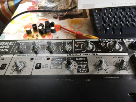
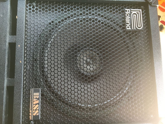
Roland Cube 100 Bass
Now discontinued, these are great practice amps or for quiet gigs. This one we have has been well used and now a bit damaged, something large and heavy being dropped on it, so needs fixing.
When I came to do this I couldn't find a lot of info on the internet to help so here are pictures of the breakdown for anyone who's interested.
I had problems finding the service documentation for the amp so here its is. The actual user manual is on Rolands website here.
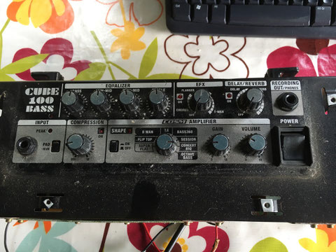
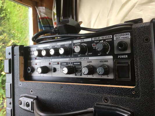
Amp module just removed from the main case, covered in dust in the picture but in life didn't look to bad. Generally appeared ok but the bass and compressor controls had been pushed into the fascia, pushing the circuit board below down and with it the switches and LEDs.
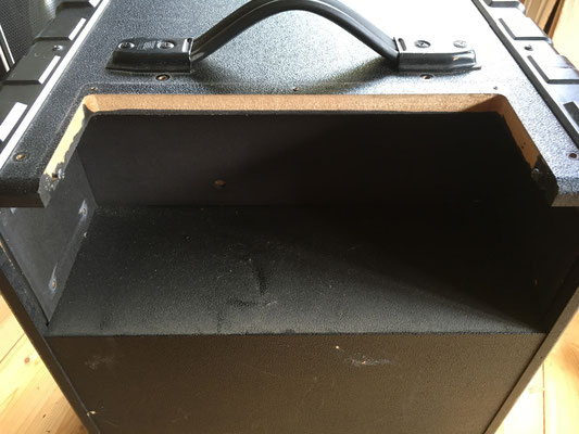
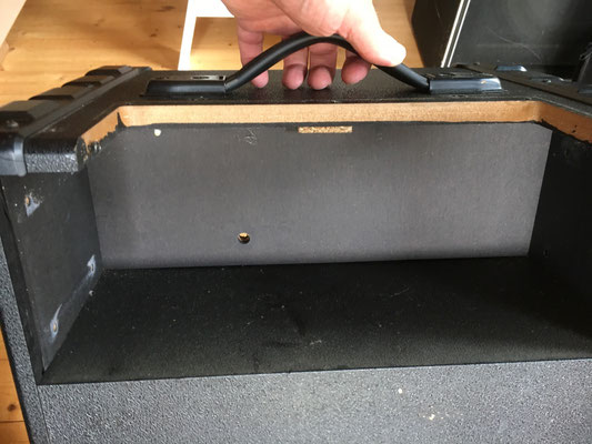
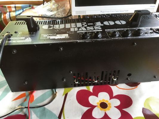
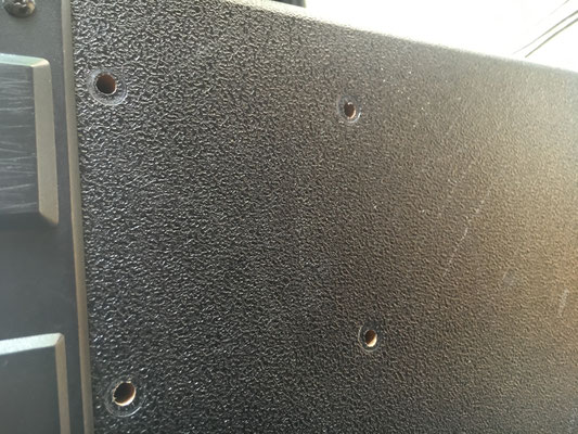
Couple of pictures of the rear of the case with the amp module removed. There were 12 bolts holding it in, four on each side and four through the top, all easily accessible. This didn't free the amp module because the speaker leads were glued in place. You can see the hole they passed through in one shot.
To remove the amp module THE SPEAKER MUST BE REMOVED FIRST AND THE LEADS FREED UP. Then the amp module can be unscrewed and removed, feeding the speaker cables through as it comes out.
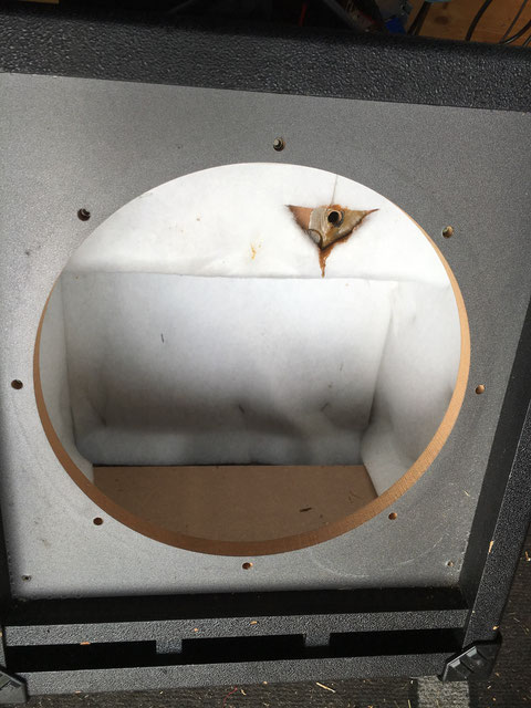
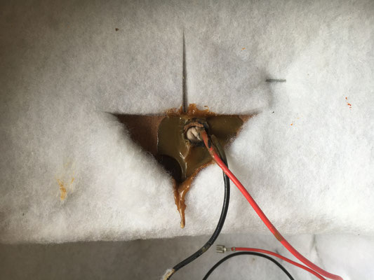
Nice big picture of the front of the case with the speaker removed. There's a port at the bottom and 8 bolts holding the speaker in. At the rear is the hole where the leads go back into the amp module and the glue which was used to hold them in. There was also a sponge grommet in the hole which according to the manual has to be replaced each time, not surprised if it's glued in. I'll probably fill it with an ear plug when it goes back together.
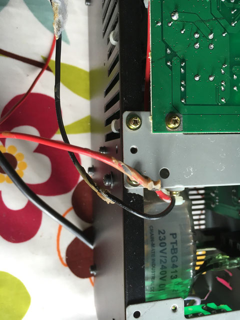
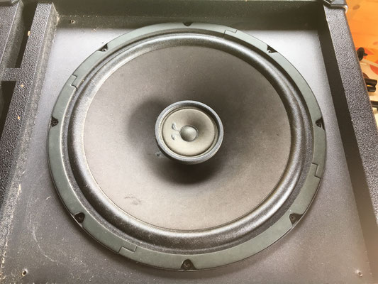
Picture of the cleaned up glue on the cables. Not really happy with that, does it improve the sound quality? For completeness, here's the speaker, a custom job for Roland I think.

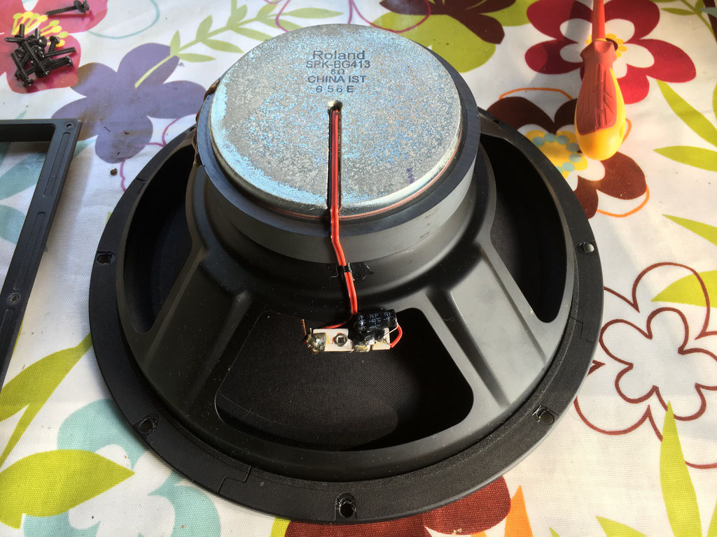
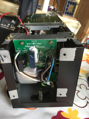
The speaker has a well compressed foam gasket on the rear, as well as a capacitor soldered in to provide a degree of cross over filtering on the tweeter. The wires attach to push on clips on the small circuit board which is positioned at the bottom when the speaker is installed in the case.
Now some views around the amp module just to give a view of what's in there and how many screws and bolts are in use. A bit of trim was also unscrewed and removed to prevent damage.
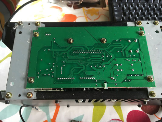


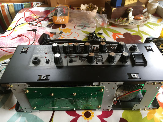
The whole point here was to repair the controls so now some views of what had happened. First to come off was the power amplifier board which is on the rear of the module, held on by eight small bolts, one of which also attaches an earth lead.

The picture shows how the control board is bowed downwards by the damage. For a 100w combo, not a very big heat sink. The amplifier IC is on the other side and shown in the next picture for info.
The control panel is attached using only the nuts holding the controls in place. There is a separate circuit board for the amp modelling selector but it's attached via a short cable so has to be removed at the same time.
All the knobs were just push fit, except for the modelling control, which was glued on, yup more glue. Undoing all the control nuts was easy and the panel comes off by itself, the jack plugs and power switch are all attached separately.

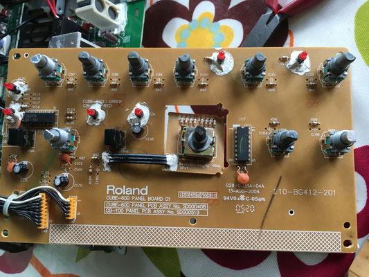
That's the board removed and the damage is obvious. Once removed the board sprung straight again. The compress control is gone completely, the bass is torn but still holding together, and while I was inspecting everything, I found the volume control was badly damaged as well. From the scraping on the fascia, wasn't just me using it broken. So three controls to replace. You can see the separate circuit board for the rotary switch, no idea why except possibly a different height. The whole board is just to create control signals for the circuits below, no actual audio comes near.
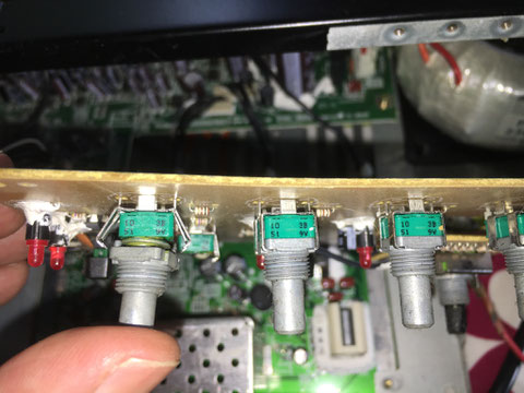
Close up of the pots. They are all identical 10K units but finding an off the shelf replacement was difficult, again these appear to have been made for Roland by Alps. I put a meter on to work out what they were doing.
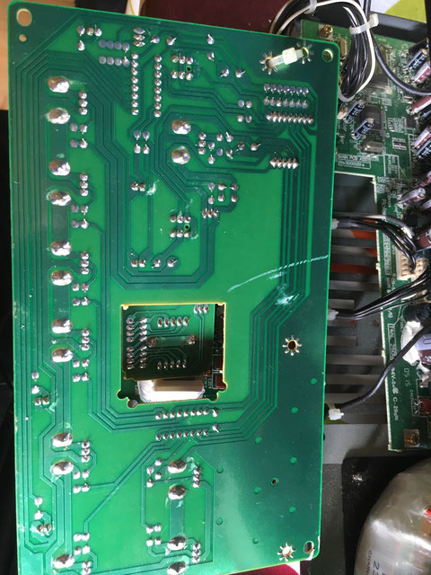
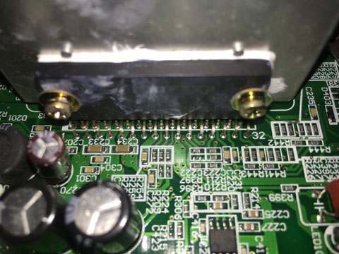
And the rear of the control board which I'd have to de-solder the controls from. The white streak appears to be from when I removed the power amp board and the droop on the control board meant that it was lying on the heat sink, though the rest is heat sink compound so maybe not just me.
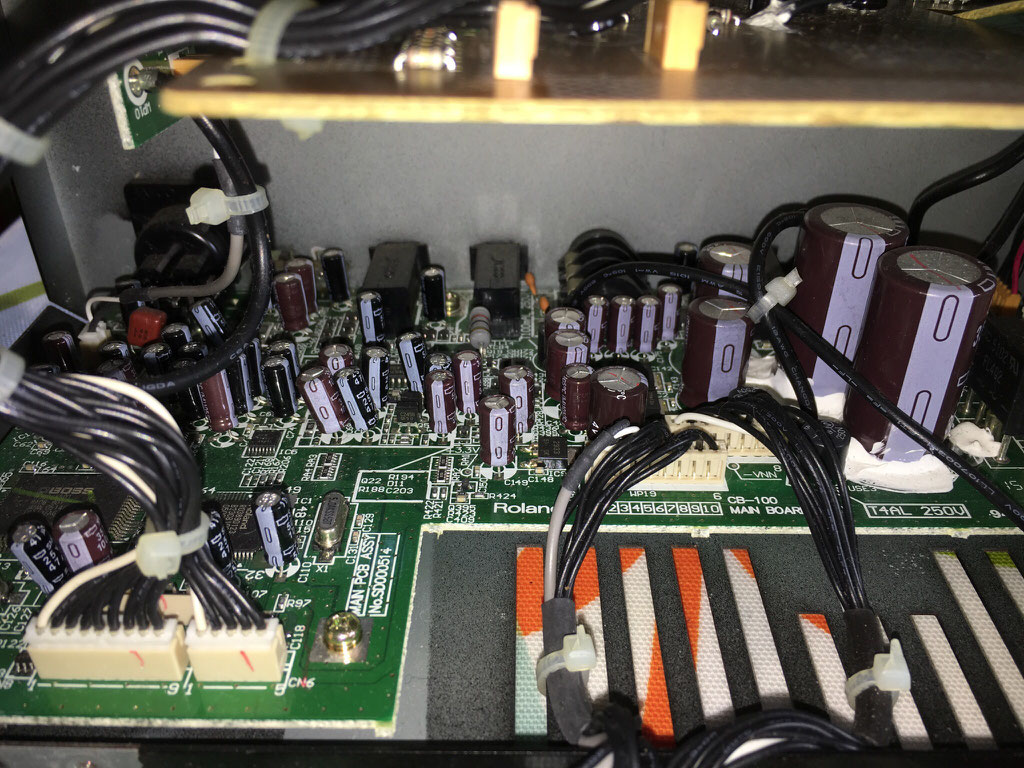

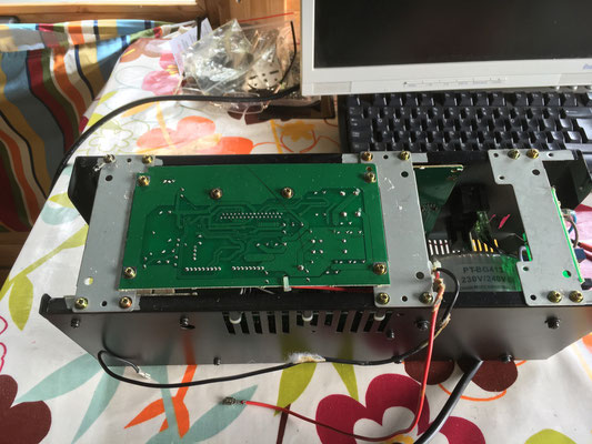
Couple of pictures of the logic and processing board, ICs to the left, power supply to the right. For a bass amp, fairly lightweight smoothing.
The Repair!
So having disassembled the amp it needed fixing. A quick check of the service manual gave me the replacement part no. but while it looked like a standard Alps part no, it didn't actually decode to a real off the shelf part, probably a Roland only piece. Lots of very similar parts but not it. Using the codes on the side of the installed parts, it was a 10K potentiometer with a 3B resistance taper, otherwise called a 'volume control'. This isn't logarithmic, it's just tapered to give better subjective control of volume when used for that purpose.
In the case of the Cube 100, all the variable controls are there to provide a control voltage to the main logic circuits and don't handle actual signals, so while they have to be the same, it doesn't affect the quality of the sound. Just to be sure, I decided to hold off buying an equivalent, remove the parts and test them.

So here's a pretty picture of the control boards without the broken controls, and yes, they had a 3B taper.
It would have been good to be able to get an exact equivalent, but in the end I bought four Alps RK09L1140A2U from Estonia as that's where I found someone with them in stock and for sale in small quantities.
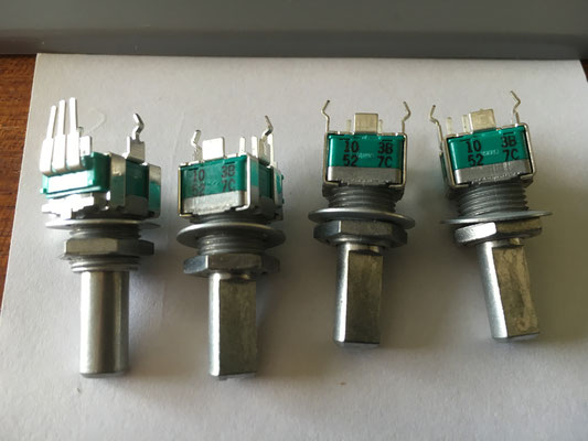

So there's some pictures of the replacement parts, and from the side by side the control shaft is longer, 20mm, as is the fixing thread, but the shoulder on the shaft is at exactly the same height from the base in both parts so will keep the knobs at the right height, once the shaft has been cut down!

Five minutes with a hacksaw and all three are the same height as the original. Now just a matter of soldering them into place, reassembling and testing.

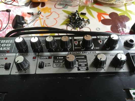
Now that looks better, all the controls are the correct height now, could still do with a clean up (found a certain amount of chocolate melted here and there!).
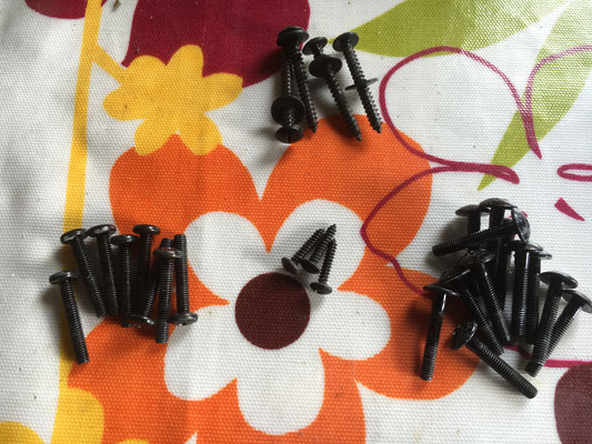


This is a selection of pictures for completeness.
The first just shows the screws and bolts for assembling the case. The three small screws are for fitting the 'C' shaped piece of plastic trim, shown in the next picture, which only seems to hide the edge of the wooden case. There are twelve bolts holding the electronics into the case, four on each side, and four in the top, shown in the next two pictures.
As mentioned before, the speaker leads are threaded through a small hole and were originally glued. The picture shows them back in place and the hole bunged up with a new piece of foam, well actually a new ear plug, and not glued!
To finish off, the speakers is attached to the leads using the clips, the speaker refitted, and bolted down using eight bolts and finally the front grill refitted using four screws. The front grill had been knocked about a bit so two minutes bending it back into shape before fitting improved the look of things.
And that was that, plugged in, fired up, and worked first time, took it out and played that evening. I'm not a reviewer, but while it may have been popular, this amp isn't good at low volumes and really has no worthwhile character of it's own. Wind it up and use the amp modelling effects and it comes alive, but it is just electronics, not much else. Could probably be improved with a beefed up power supply, bigger capacitors certainly, and the speaker isn't great, but ultimately it works and would it be worth it?