
Family Monitor Hardware Design

The picture above shows a completed monitor plugged into a wall socket. This is still very much a prototype design, with the ESP32 usb socket visible for modifying the firmware.
The unit is positioned in a location where it will be able to detect normal activity of the family member, but not an abnormal situation, such as someone lying on the floor.

Above is a breadboard layout diagram of the prototype monitor.
From the left, a mains transformer provides 9V dc via a bridge rectifier and smoothing capacitor, to a LM317 regulator set to 5V output.
The 5V supply is only used to run the SR504 PIR detector and provide a supply to the 7333 regulator.
The 7333 regulator provides 3.3V power to the rest of the monitor.
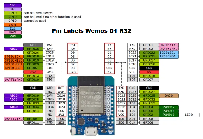
The ESP-WROOM-32 microcontroller is supplied with 3.3V from the regulator but it's circuit board also has a 5V USB supply and a 3.3V regulator which can be used to power the unit during testing.
The ESP32 is connected to the SD Card reader, three LEDs, one of which is bicolour, a programming switch and an input from the PIR detector.

This is the breadboard prototype, the ribbon cable connects the PIR detector.